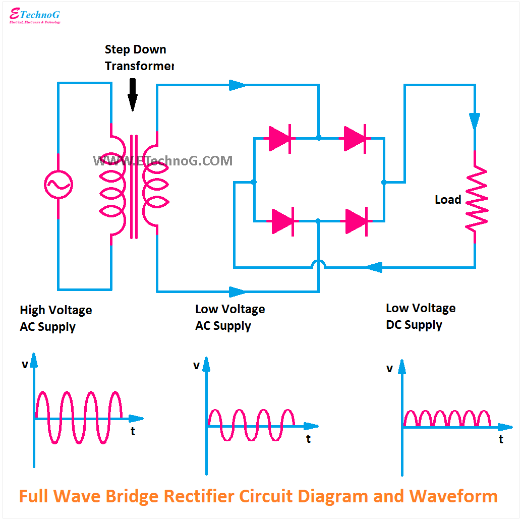
Full wave rectifier schematic Bridge rectifier circuit, construction, working, and types Bridge rectifier circuit diagram with working
Figure 7: Circuit diagram of the full-wave bridge | Chegg.com
Rectifier bridge
Full wave bridge circuit diagram
Figure 7: circuit diagram of the full-wave bridgeFull wave rectifier bridge circuit diagram Full wave bridge diagramWhat is single phase full wave controlled rectifier? working, circuit.
Full wave bridge circuit diagram[diagram] h bridge circuit diagram Full wave rectifier circuit working and theoryFull wave bridge circuit diagram.

Bridge full wave rectifier circuit diagram
Full wave bridge rectifier circuit diagramRectifier circuit diagram Explain full wave bridge rectifier with diagram pcb designsHalf wave bridge rectifier circuit diagram.
Full bridge rectifier circuit diagramFull-wave bridge rectifier circuit Full wave bridge rectifier circuit diagramDraw the circuit diagram of full wave bridge rectifier.
Rectifier circuit waveform input
.
.


![[DIAGRAM] H Bridge Circuit Diagram - MYDIAGRAM.ONLINE](https://i2.wp.com/www.theorycircuit.com/wp-content/uploads/2018/03/full-wave-bridge-rectifier-circuit-diagram.png)
